
PCB Ribbon
| What you will need |
|---|
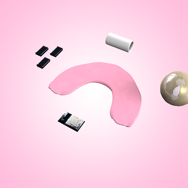
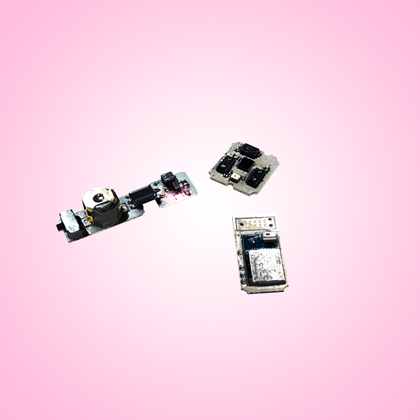
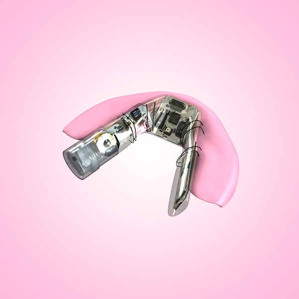
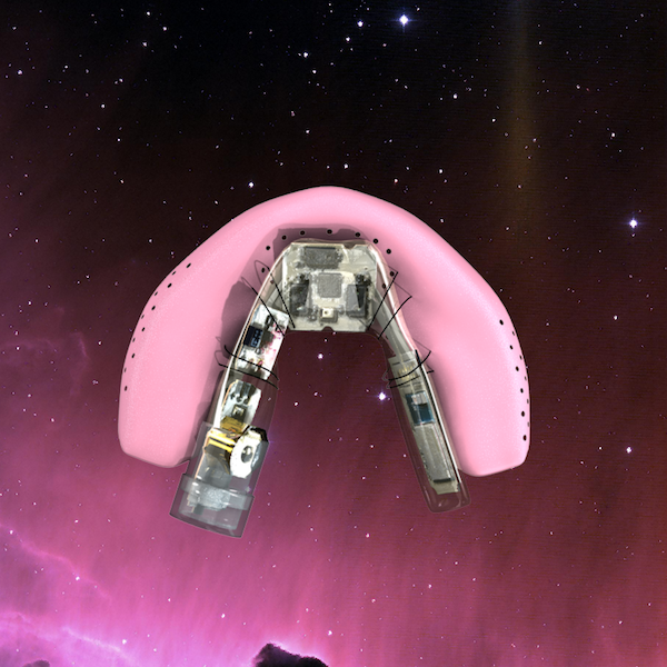
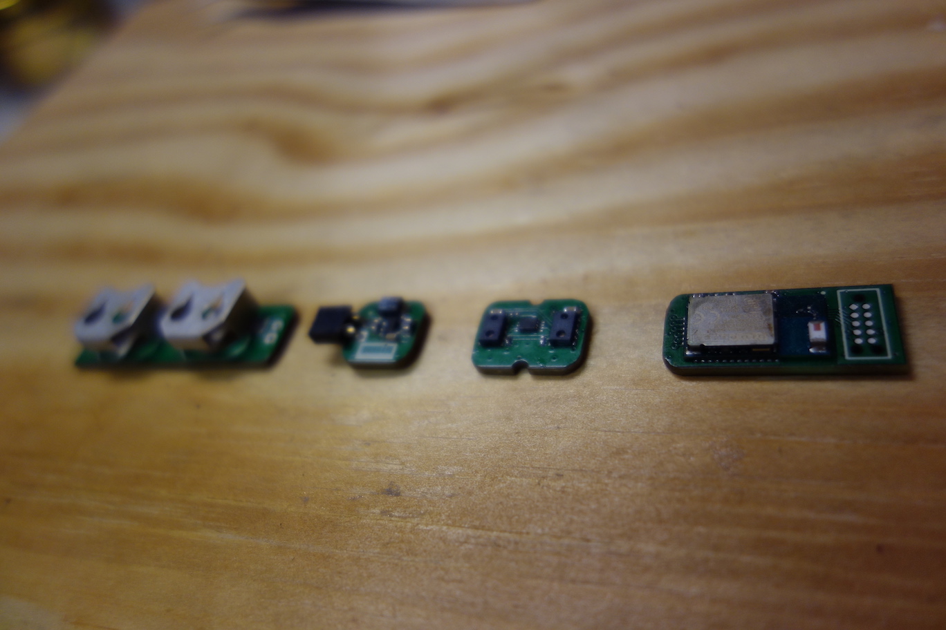
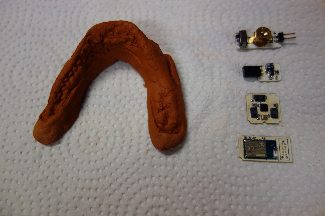
Now you should have PCBs as shown below:
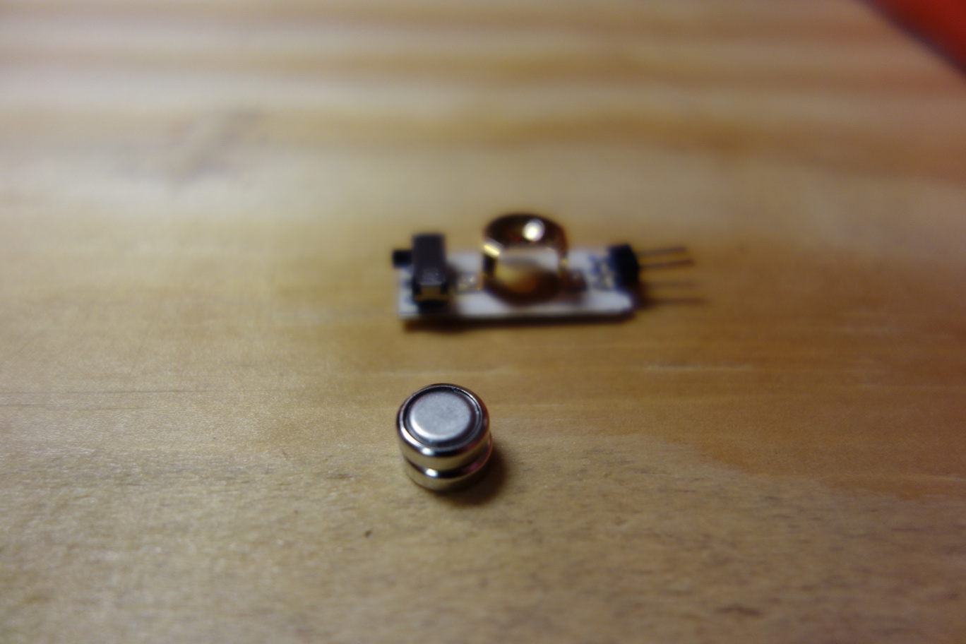
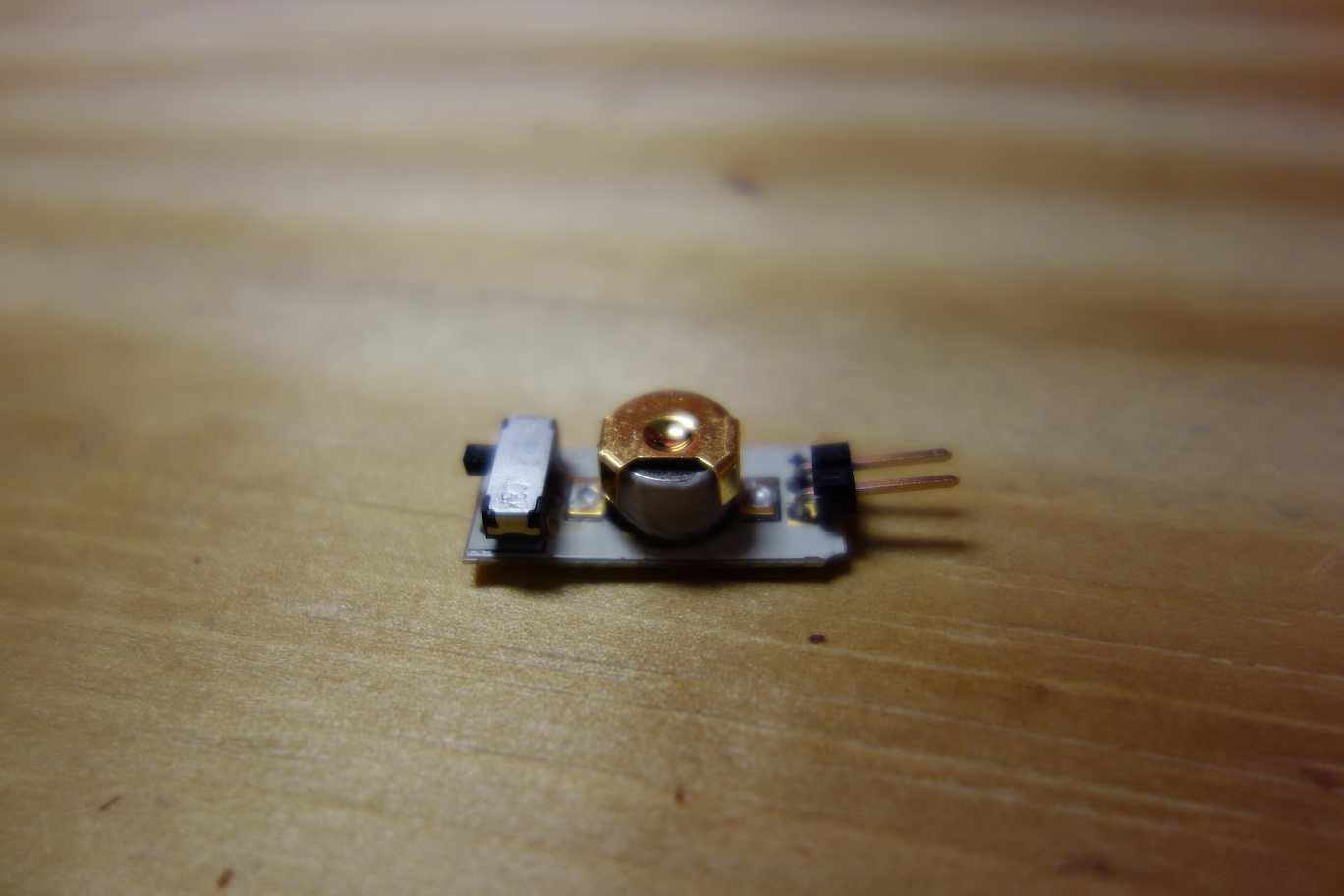
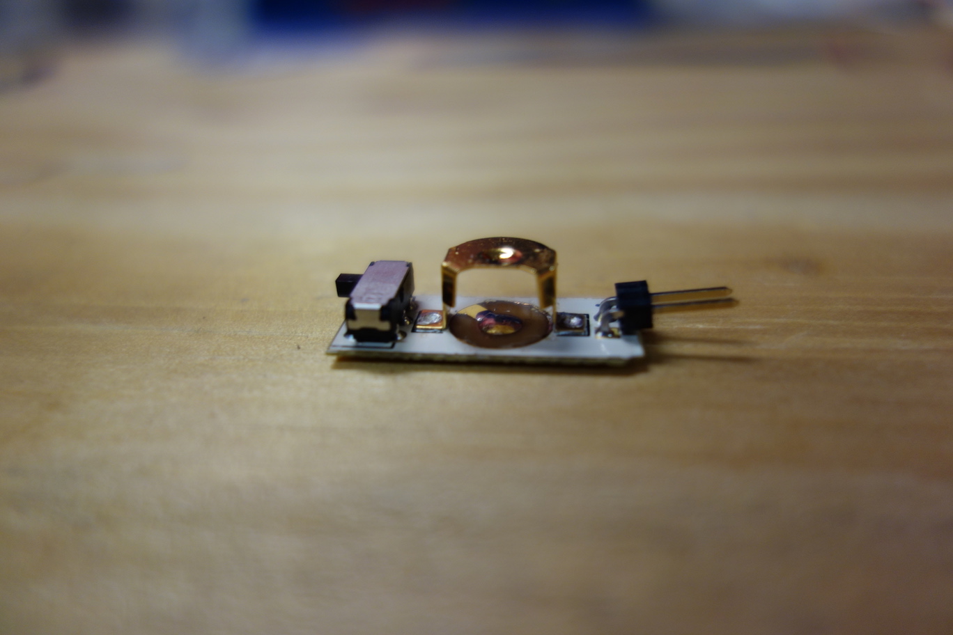
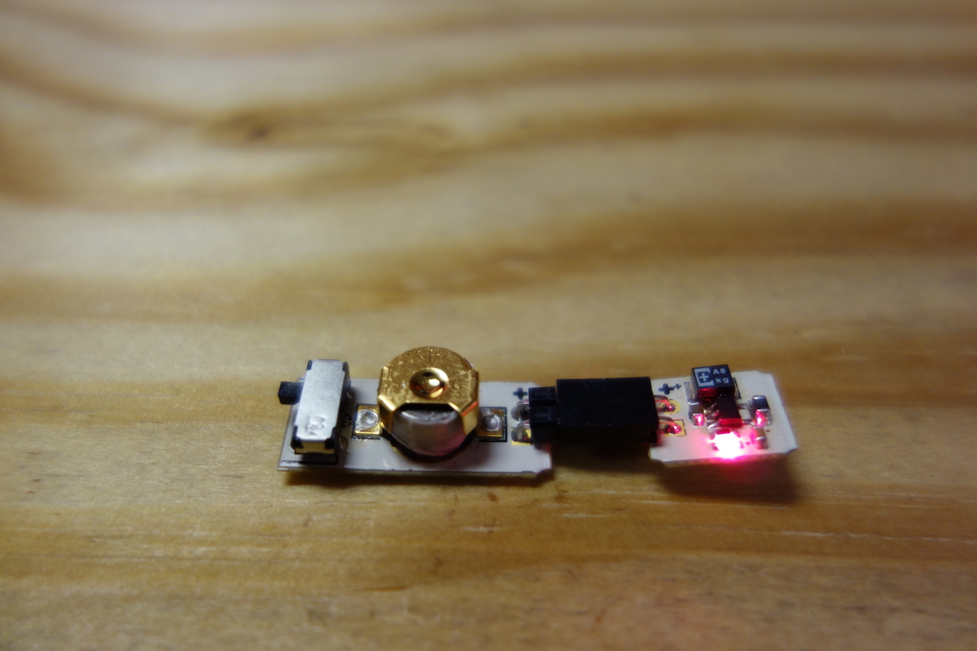
- The Battery Board
The Battery Board consists of an on/off switch, a battery holder for two 376/377 cell batteries, and a male header to connect to the Voltage Regulator Board. This board outputs a voltage of 3.1V if the batteries are new. The Pallette circuit will continue to function until the battery voltage drops below 2.2V.
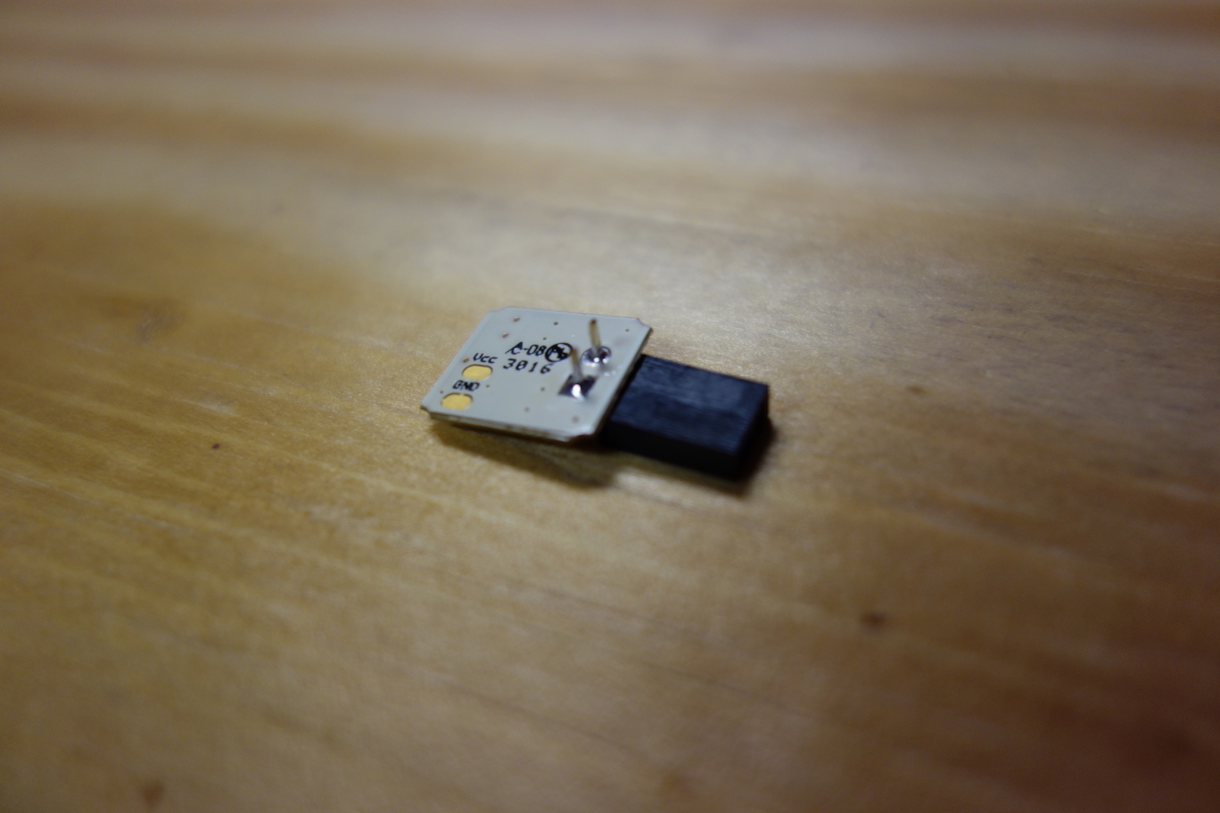
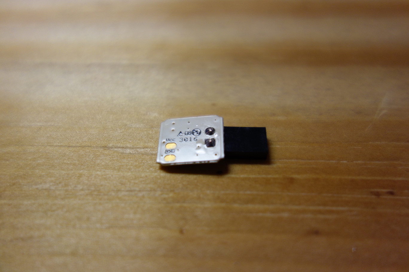
- The Voltage Regulator Board
The Voltage Regulator Board converts the voltage from the Battery Board to 2.2V. It automatically maintains this voltage level to protect sensitive electronic components and ensure consistent sensor readings.
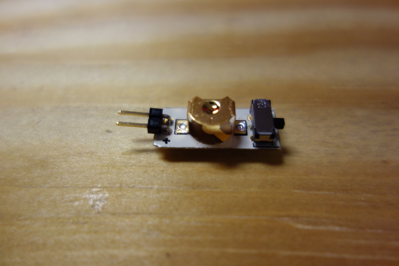
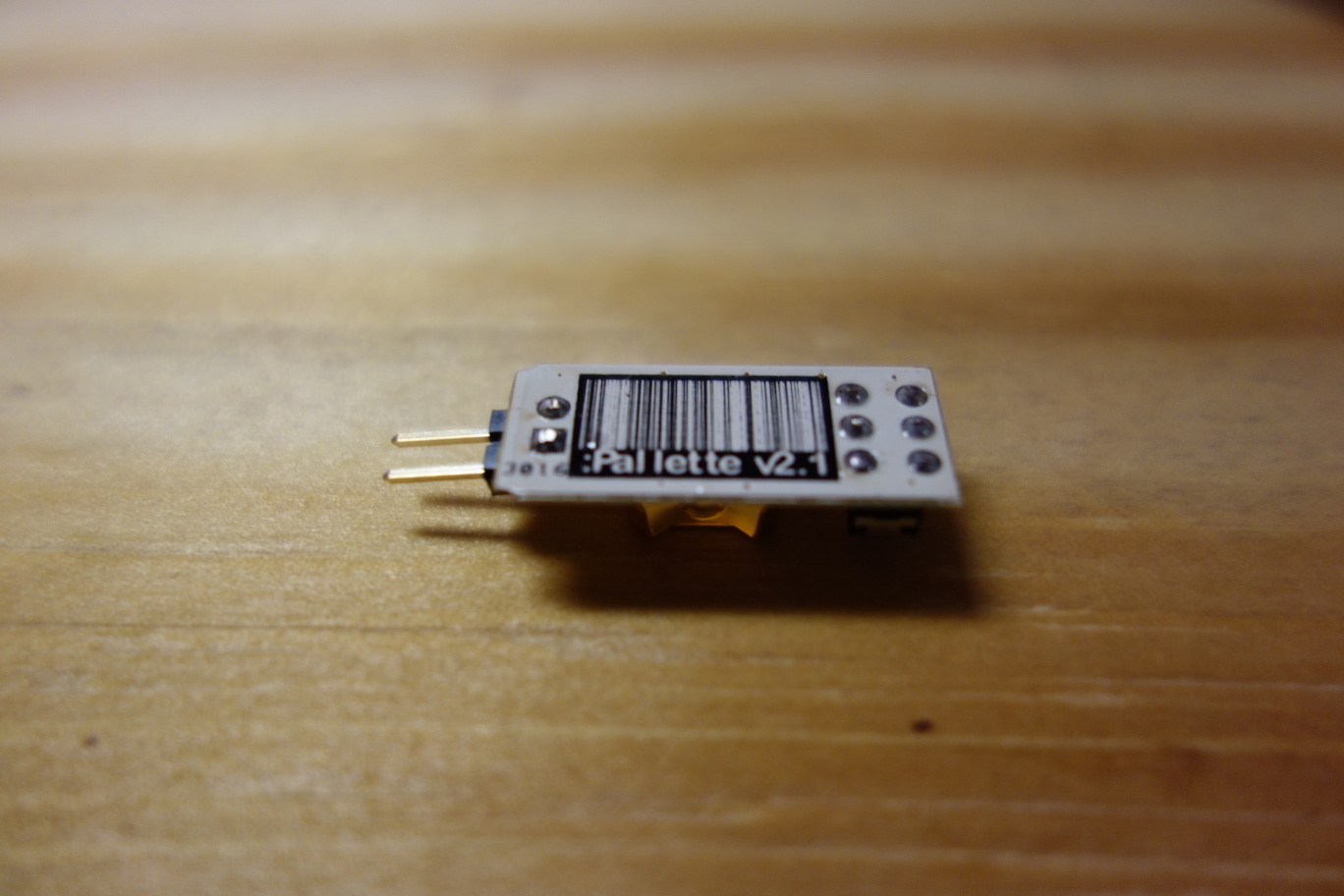
- The Sensor Board
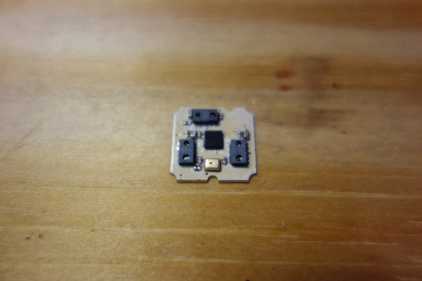
The Sensor Board has three infrared sensors, which are strategically positioned to track tongue movement accurately. It also has a golden microphone chip which detects tongue tapping, in order to register a selection.
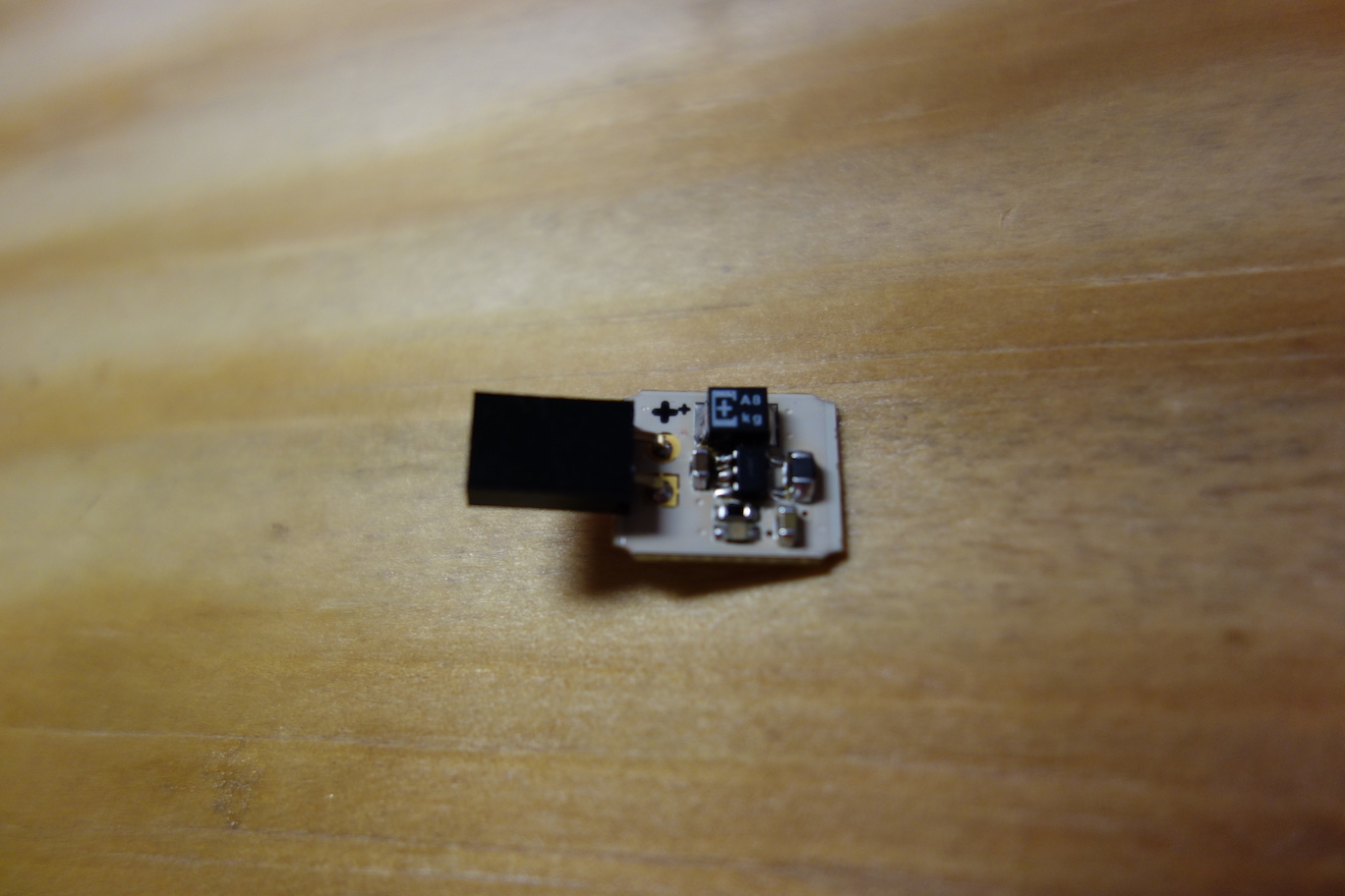
- The Microcontroller Board
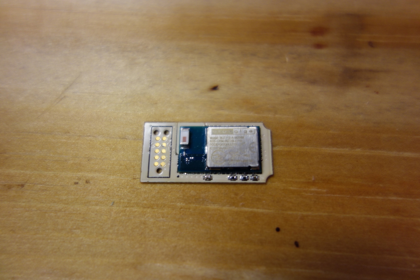
The Microcontroller Board consists of a Bluetooth enabled Bluegiga BLE113 microcontroller and an in-circuit programming footprint. The microcontroller enables Pallette to wirelessly communicate with a computer or a mobile device. The programming footprint allows developers to program the microcontroller, either with our firmware, or their own firmware.
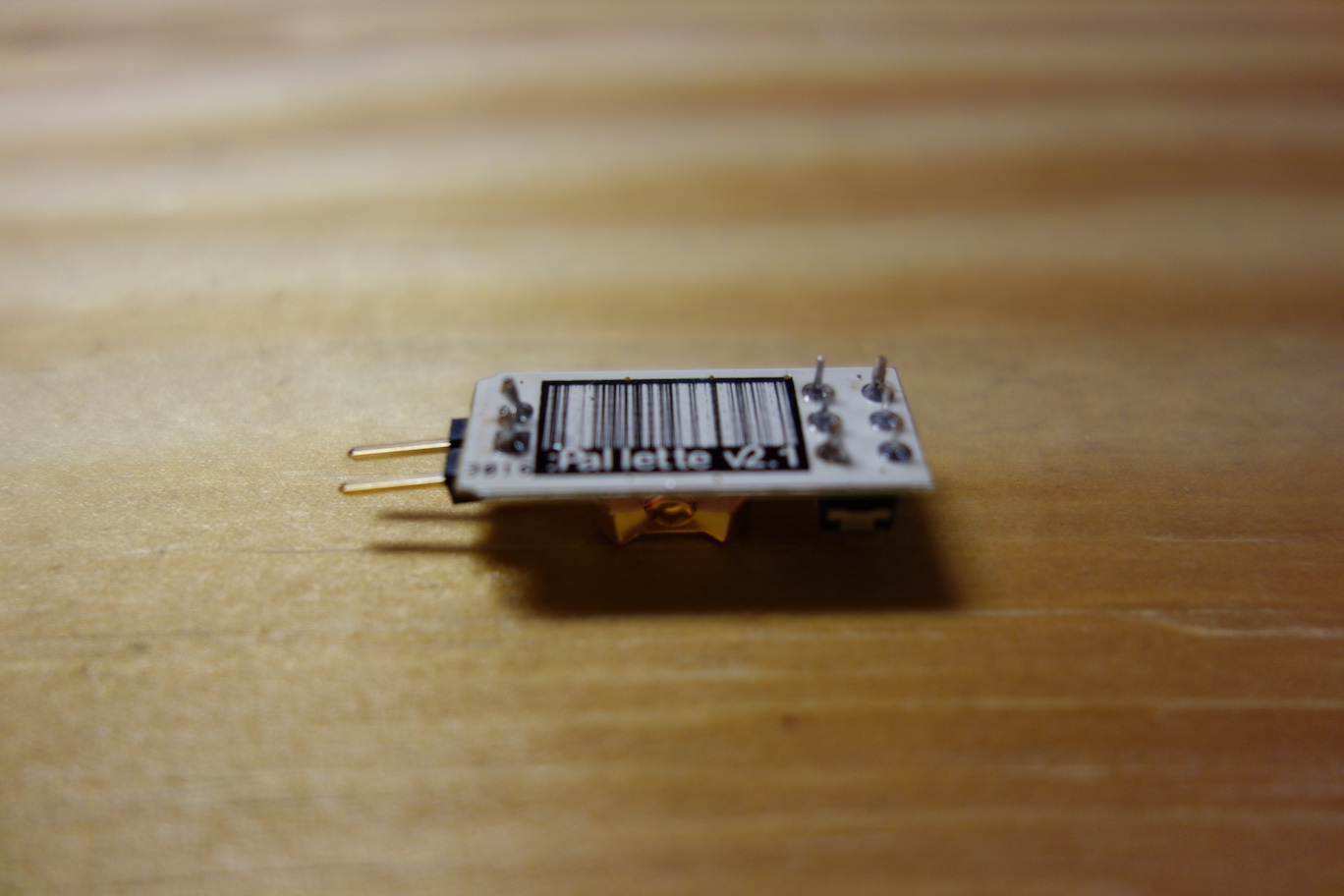
If you ordered the 0.062" green PCBs, they will look like this (photo features an older design):
Trim the leads
First, we need to trim the leads of the connectors with a cutter, so the leads won't poke holes on the heatshrink when we seal the electronics in Step 6. Cut off the full length of the exposed leads, leaving only the solder joints with a smooth surface.
Next, we better test the boards individually before we connect them together.
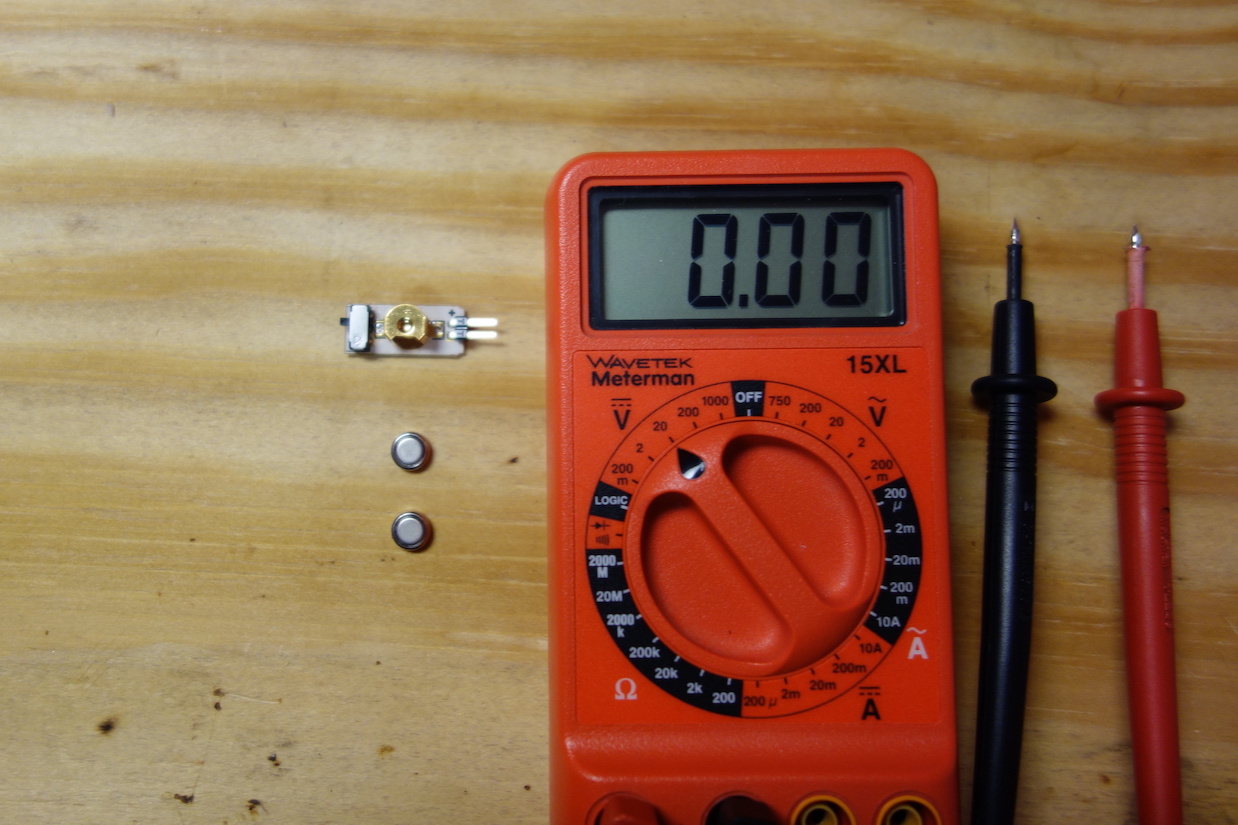
Test the Battery Board
You need two Energizer 376 cell batteries and a multimeter.
Stack two batteries and tape their side together.
Push the batteries inside the battery holder, positive side (flat side) up.
If the batteries are too loose in the battery holder, add a bit of solder to the central round pad under the battery holder.
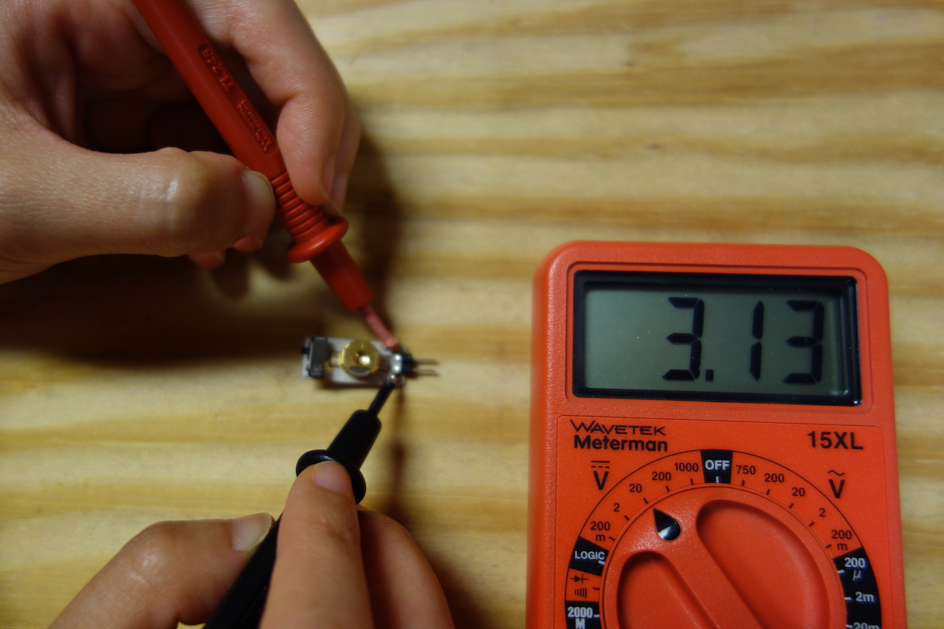
Turn on the switch by flipping the lever up, and measure the voltage across the 2-pin header, the reading should be around 3.1V.
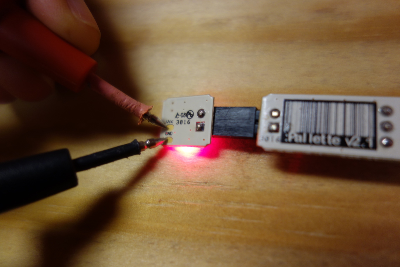
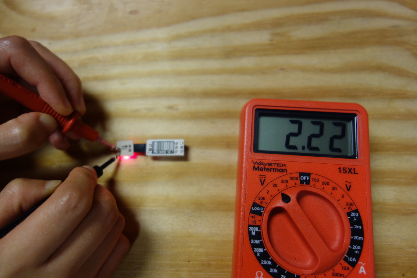
Test the Voltage Regulator Board
Plug in the battery board to the voltage regulator board, and turn the switch on.
Measure the output voltage from the regulator using the pads on the back of the board. The multimeter should read 2.2V.
The Sensor Board and the Microcontroller Board can only be tested in the completed circuit. So next, we're ready to craft the heart of Pallette - the sensor ribbon.
Connecting boards
You'll align the boards against the clay imprint you made in Step 2, measure lengths and angles for ribbon cables, and solder everything together.
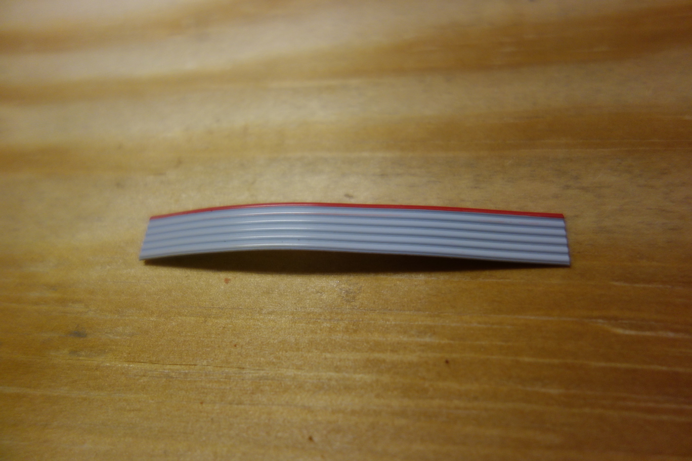
The pads on the back of the boards have a pitch of 0.05", so we will use 0.05" pitch ribbon cables to connect them. We need a 2-conductor ribbon cable to connect the Voltage Regulator Board to the Sensor Board; a 2-conductor ribbon cable and a 6-conductor ribbon cable to connect the Sensor Board to the Microcontroller Board. A 2-conductor ribbon cable can be made from a 6-conductor ribbon cable, by tearing 2 conductors off. The red wire on the cable indicates pin 1. Initially, we cut these three cables to 5cm.
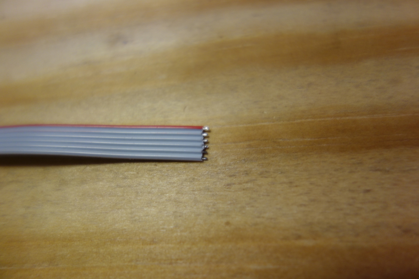
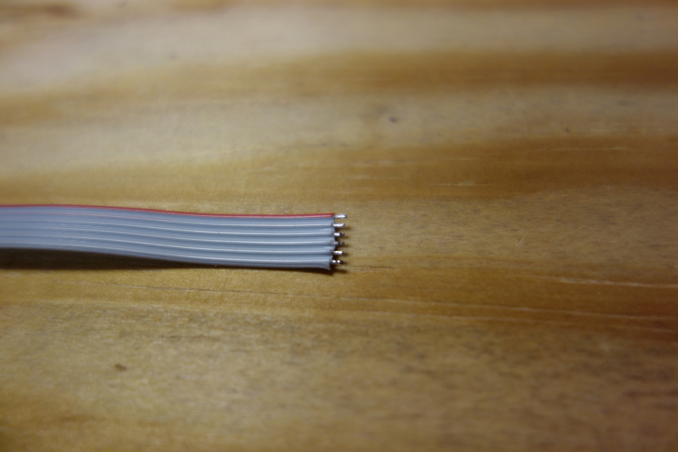
Strip one end of the ribbon cables using wire stripper.
Turn on the soldering iron, keep the temperature at 250°C (480°F). There are fragile components on the boards, so don't keep the hot iron tip on the boards for too long.
First, we need to tin the wires, so they will be easier to solder. Below is an instruction video on tinning.
Now the wires are tinned.
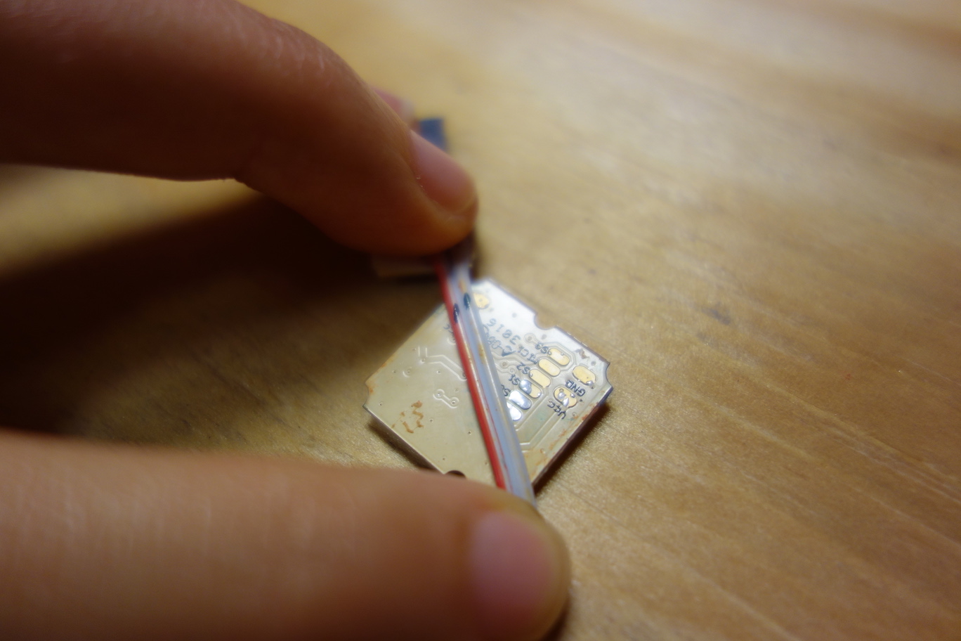
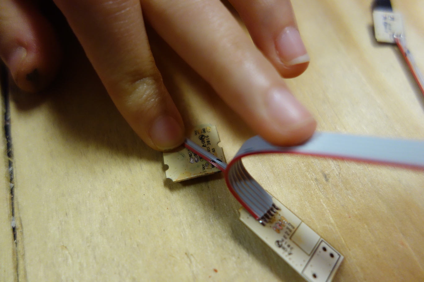
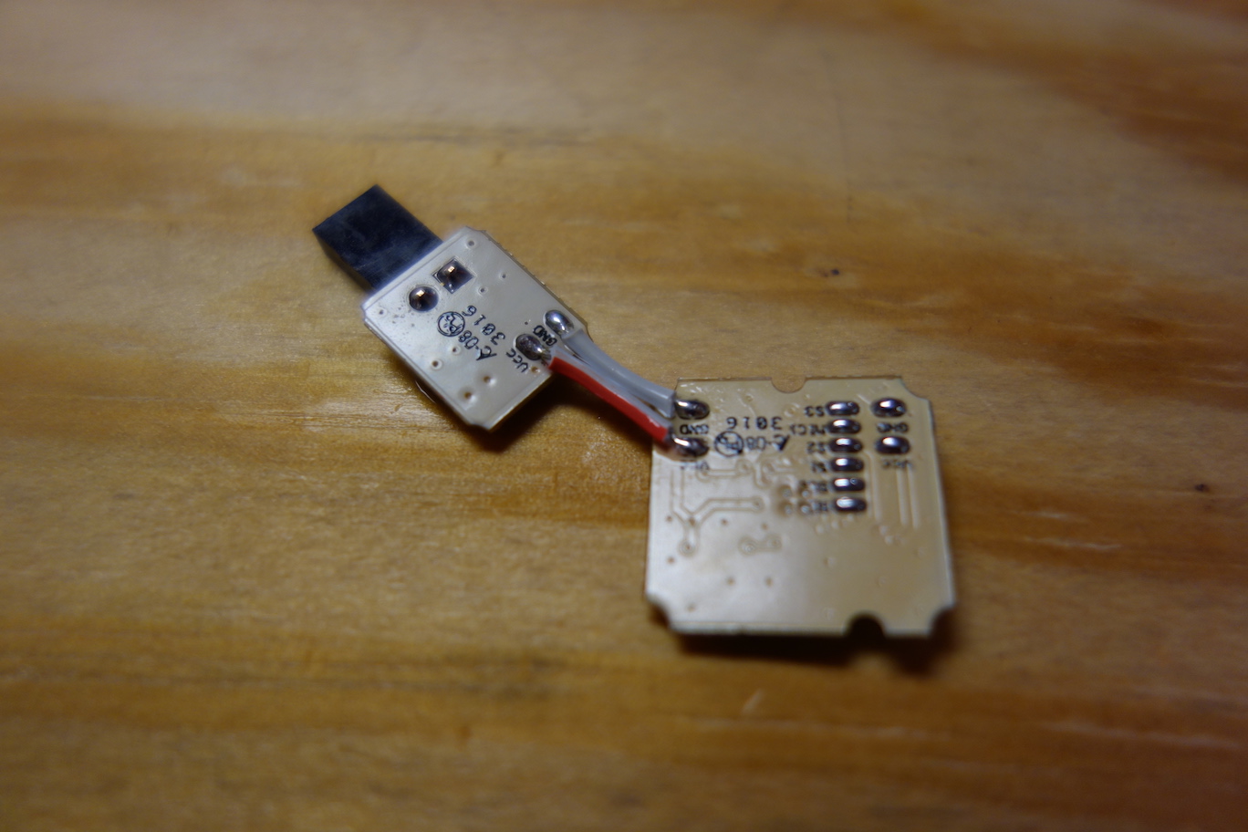
Next, we need to solder a 2-conductor cable to the back of the Voltage Regulator Board. Refer to the photo below for the direction of the cable.
It's better to add solder to all the pads first, so it will be easier to solder the wires to them.
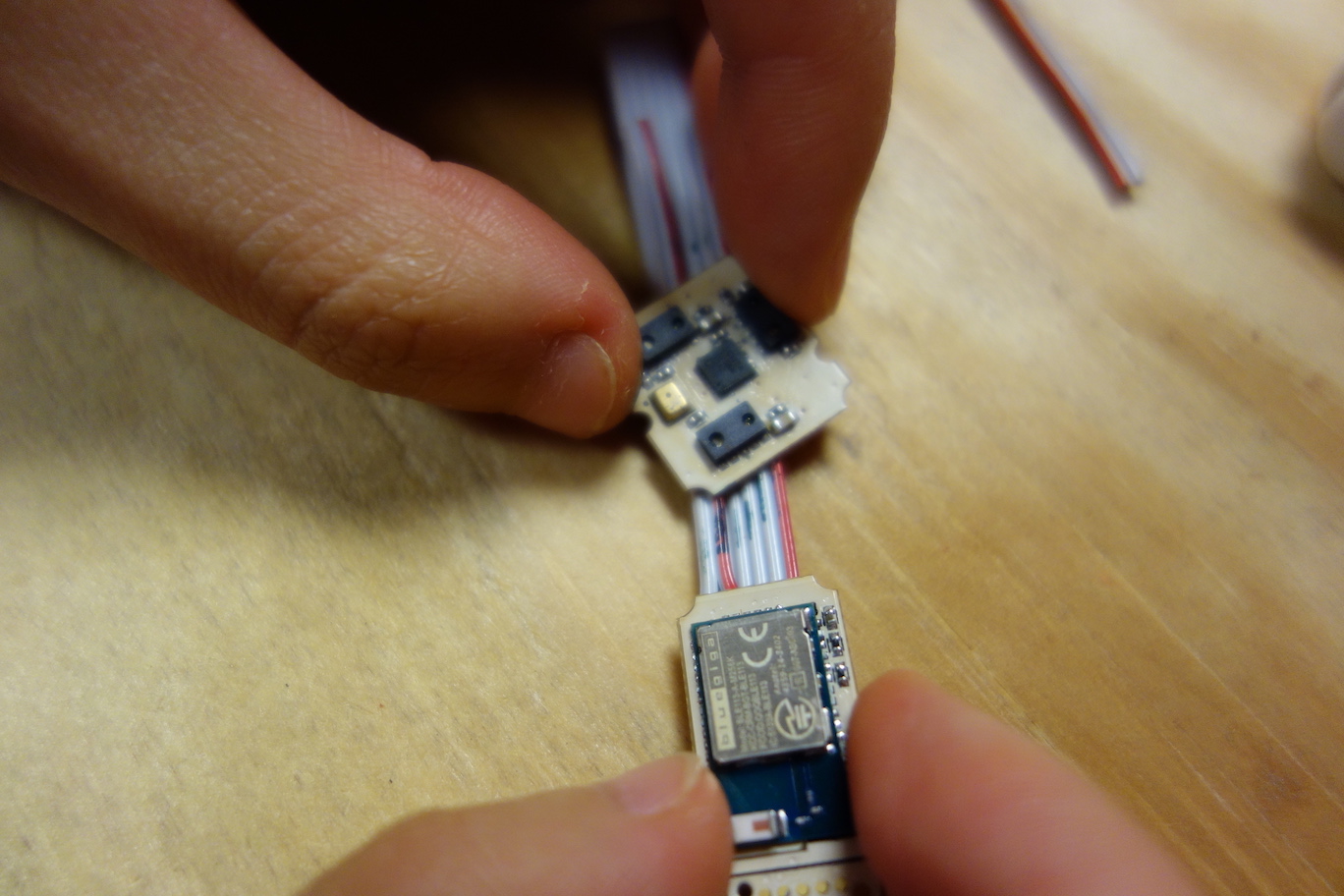
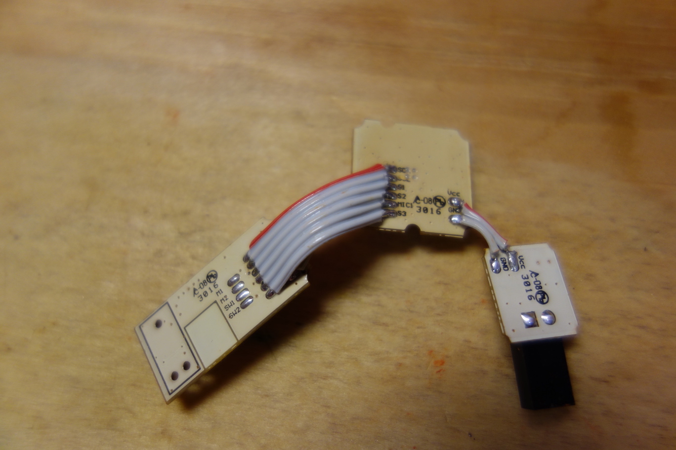
Next, we solder another 2-conductor cable to the back of the Microcontroller Board, and then solder a 6-conductor cable to the Microcontroller Board.
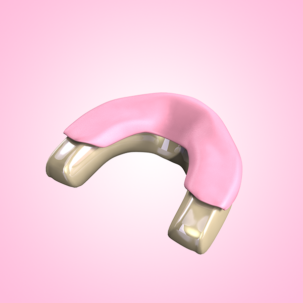
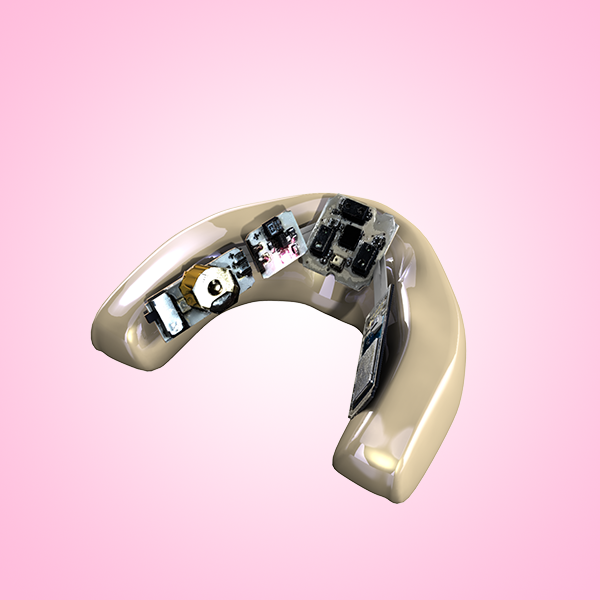
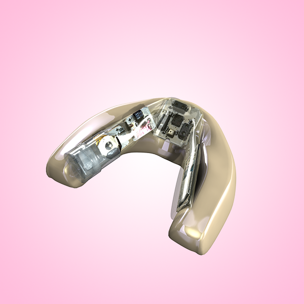
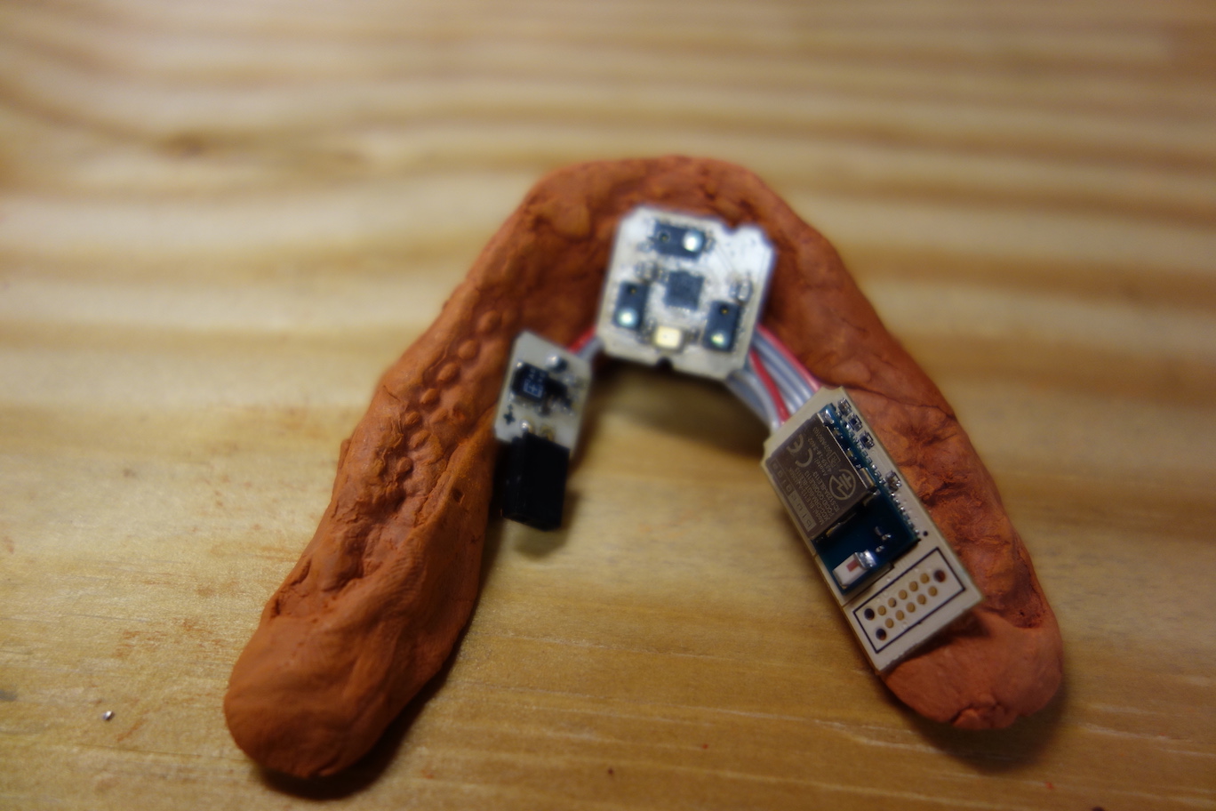
Finally, we tape the Voltage Regulator Board to the left inner side of the clay imprint, and tape the Microcontroller Board to the right inner side, leaving space in the middle for the Sensor Board.
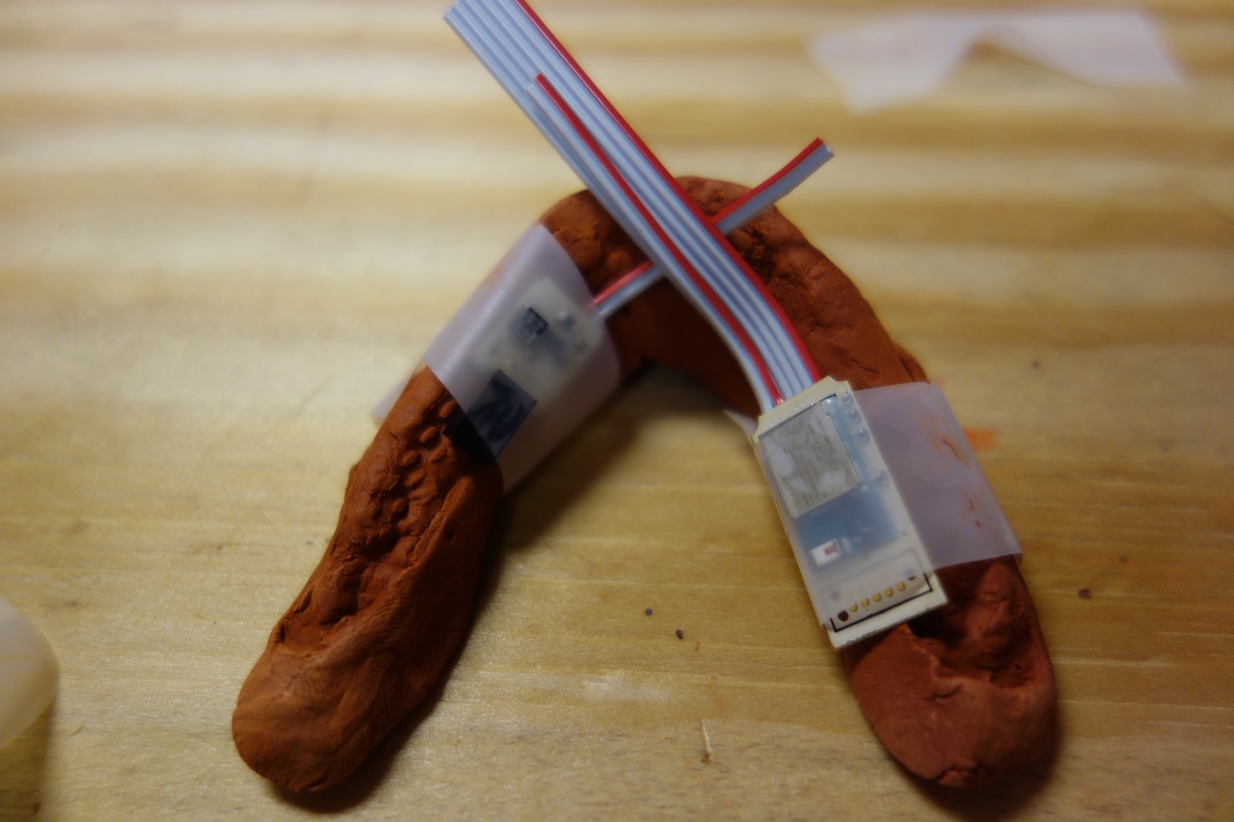
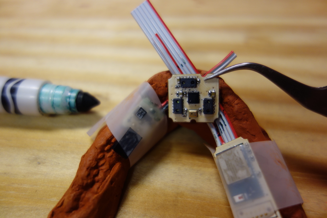
Place the Sensor Board to the middle, refer to the photo below for the orientation of the Sensor Board. Shift the locations of the boards if needed, to get them as close as possible, so the overall length of the Pallette device will be minimum. Mark the edges of the Sensor Board on the cables with a fine tip marker.
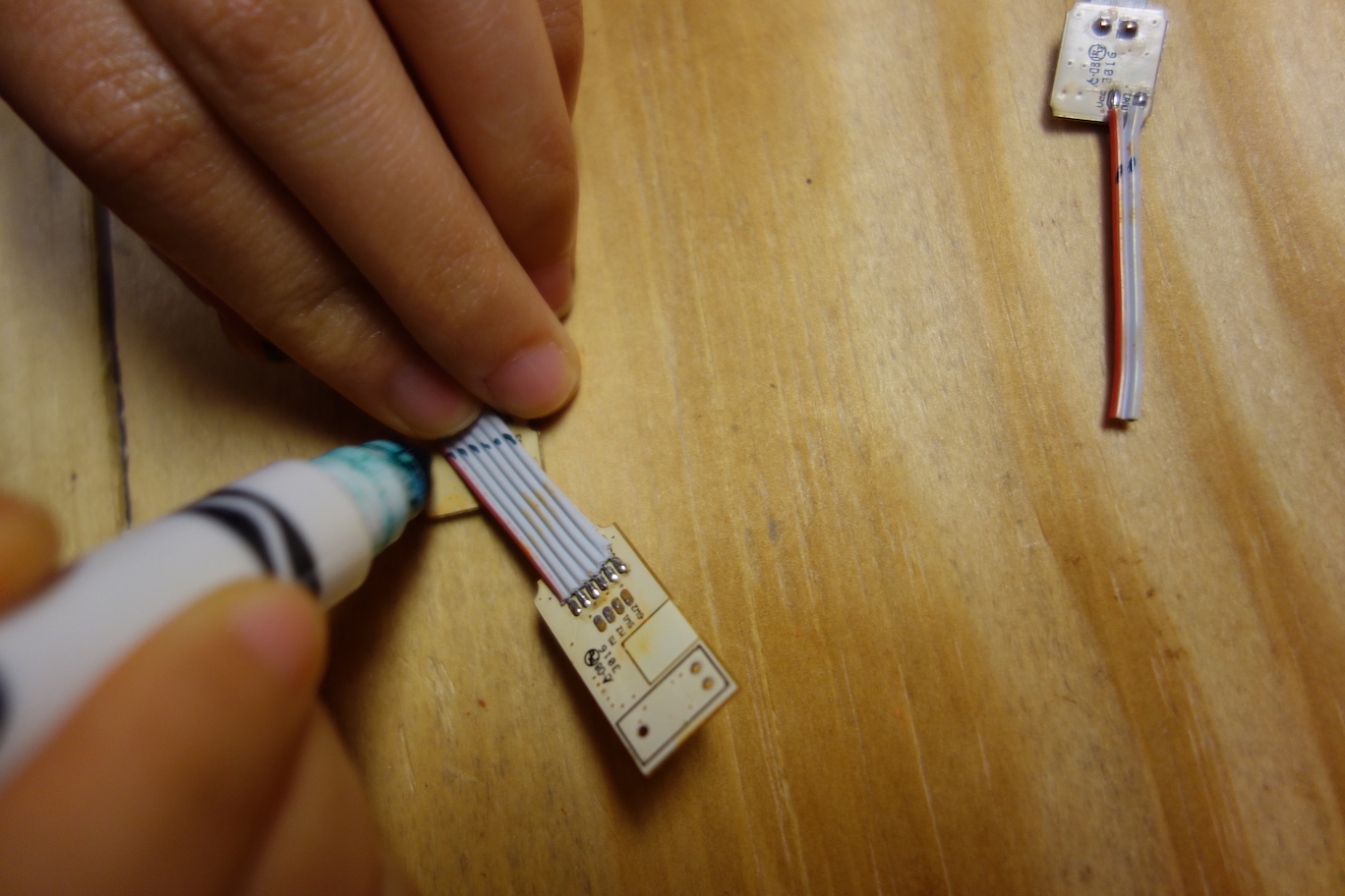
Remove the tapes on the boards. Align the Sensor Board with the Voltage Regulator Board by the marking at the front, then mark the positions of the unsoldered two pads at the left side of the Sensor Board on the ribbon cable, so we know where to cut the cable for the correct length.
Do the same to determine the correct lengths for the cables on the Microcontroller Board. These two cables go to the right side of the Sensor Board.
Cut the ribbon cables to the desired lengths, strip the ends, and solder the conductors to their corresponding pads.
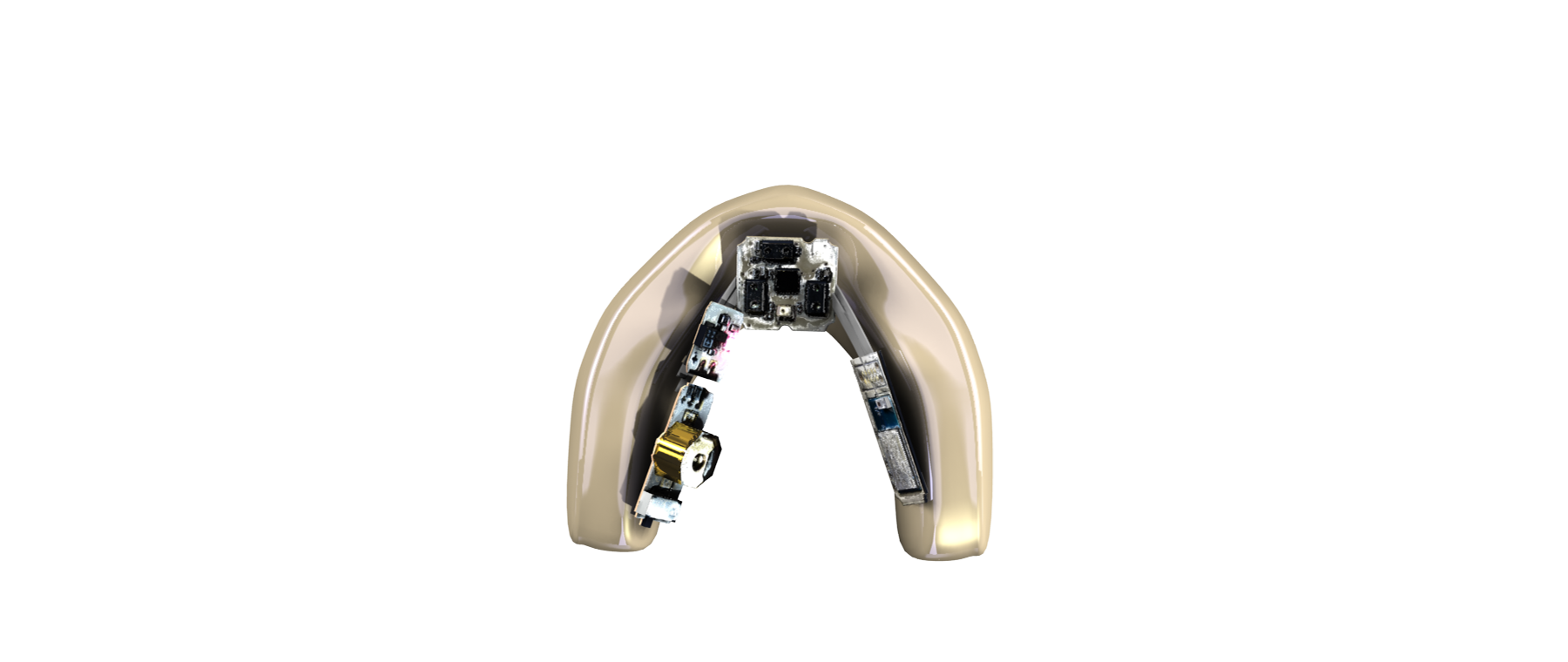
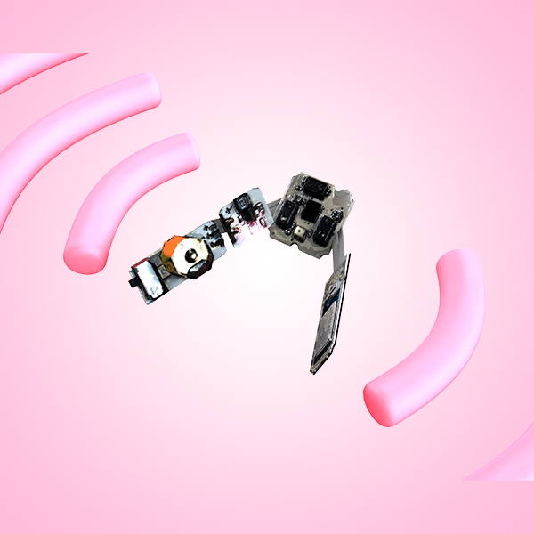
Now we have the Pallette Sensor Ribbon.
Next, we have to test the Sensor Ribbon to ensure that the circuit functions correctly, before we seal it up. The next step explains how to test the circuit using the firmware and the app.